06/01/2020
Khuzema Darugar,
CADTech USA LLC
First Article Inspection (FAI) is a method of authenticating, if a product or part has been properly manufactured according to the specifications and guidelines defined in the design. A first article inspection usually checks for dimensional accuracy of surfaces, holes, distance between features, curvatures and radii, surface finishes, and color. In this article we will take a look at how dimensional accuracy can be measured by using a 3D scanner and inspection software.
For this article we performed the First Article Inspection on a pair of fusion sockets used for welding plastic pipes. These fusion sockets are a very good example to showcase the use of a 3D scanner in inspection, as the dimensions required for inspection are hard to measure with traditional methods and can be time consuming. The first article inspection done on the fusion socket which comes in contact with the pipe is shown in below.
To perform the inspection, a detailed 3D scan of the part was required. For this project the 3D scan was created using our in-house Artec Space Spider. Once the scan was completed, a mesh was generated and exported to the inspection software.
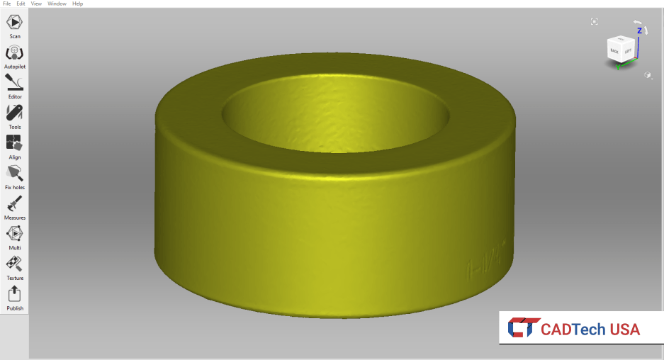
Scanned fusion sockets shown in Artec Studio
In the inspection software, we imported the scanned mesh and the CAD file. The next step was to align the CAD file and the mesh file to calculate the deviation. When aligning a part to the scanned mesh, it is important to know which type of alignment will best suit the needs of the project. For this project we used a local best-fit alignment as it gave us the best results. After completing the alignment, the next step was to input the tolerance for the CAD part, and the maximum and minimum values for the color map.
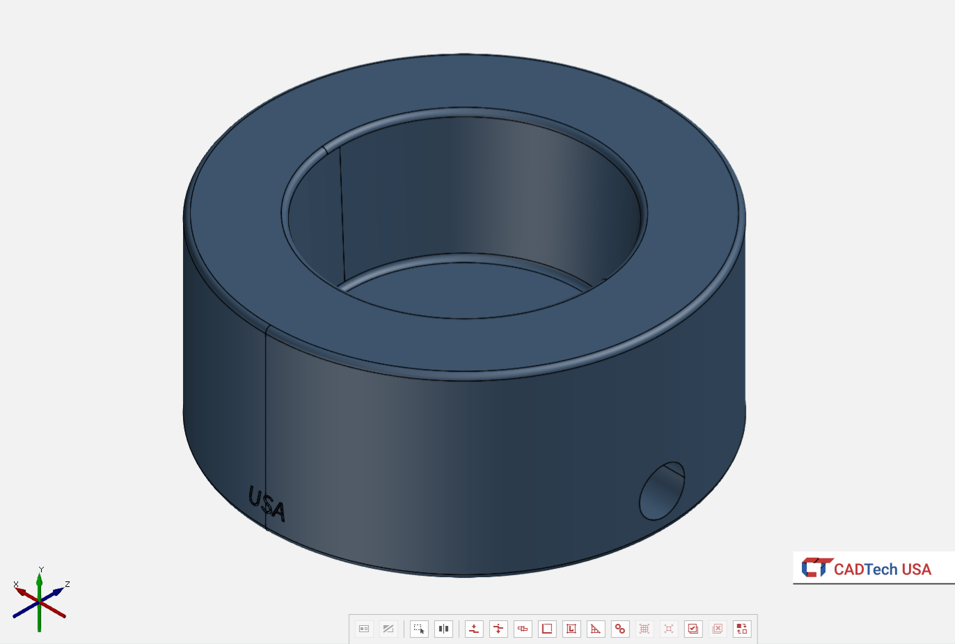 Original
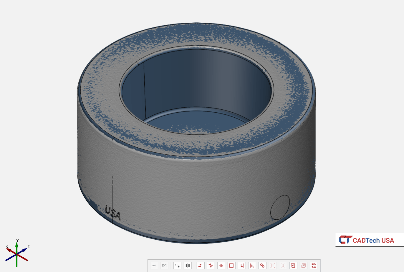 Scanned Mesh
Scanned part file overlaid on CAD file
For this project the inspection only needed to be done on the surfaces of the fusion sockets that would come into contact with the pipe. Once the project was setup, we proceeded to performing the deviation analysis between the CAD and the 3D scanned mesh. First, we performed a surface comparison to get the depth of the contact surface. Second, we did a cylindrical surface comparison to get the top and bottom diameters of the contact surface. Since the cylindrical surface has a slight taper (essentially a cone), we added two circles that intersected the cylindrical surface to get the top and bottom diameters.
Scanned Mesh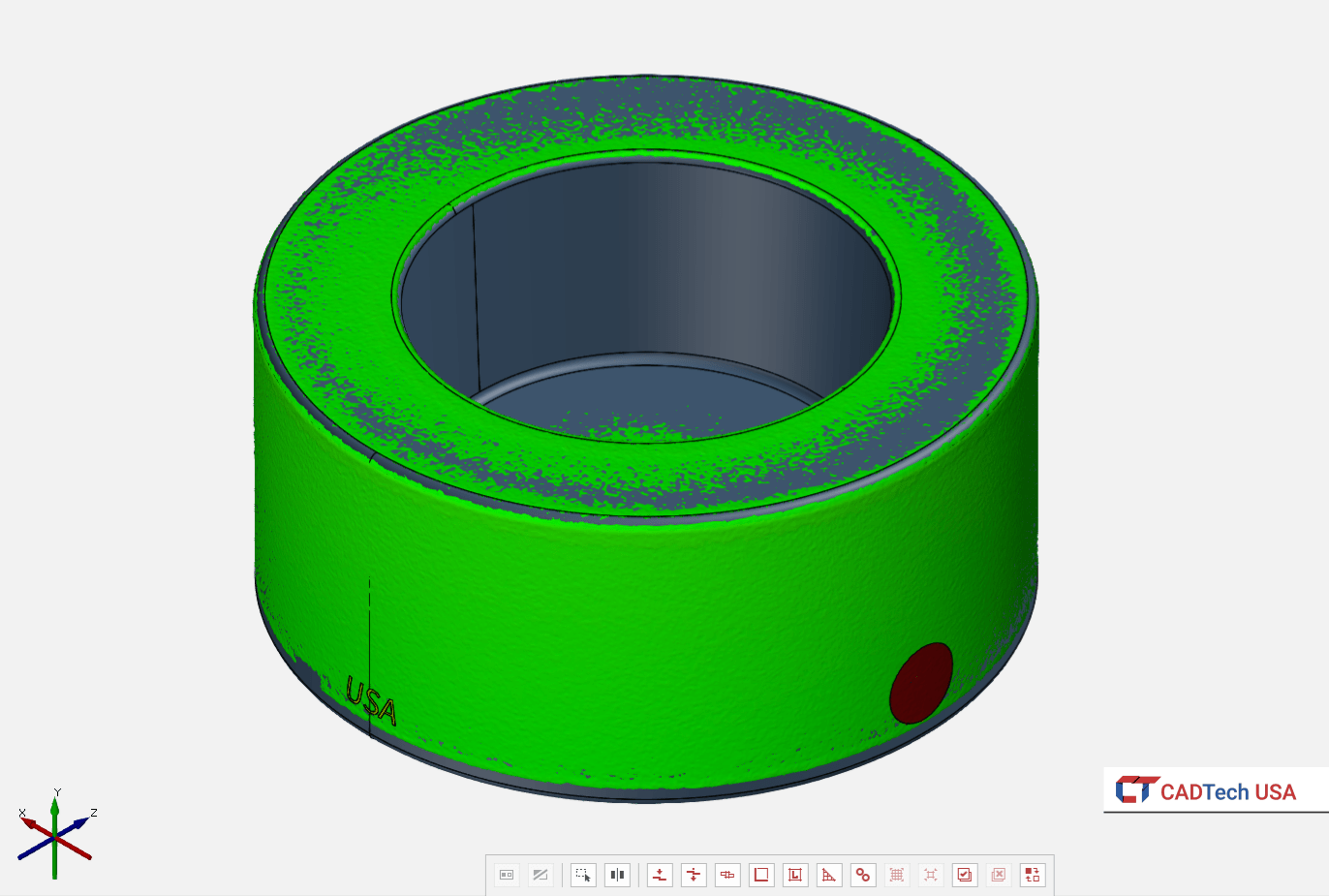 Deviation Color
Deviation Analysis on Scanned Mesh overlaid on CAD Model
The figures below show the actual and nominal values of the depth, and the top and bottom diameters of the contact surface. ‘Distance 1’ and 'Distance 2' in Figure 1 shows the nominal and actual depth of the contact surface. Figure 2 shows the top and bottom diameters of the contact surfaces. ‘Circle 1’ and ‘Circle 2’ show the nominal and actual diameter of the top of the contact surface, while ‘Circle 3’ and ‘Circle 4’ show the nominal and actual diameter for the bottom surface.
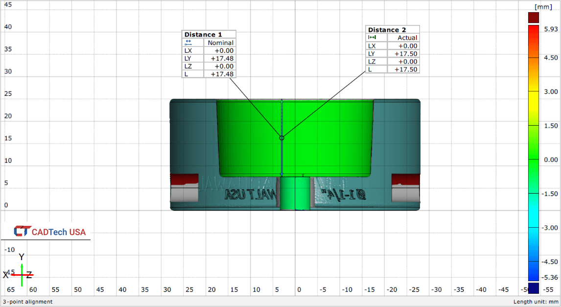
Figure 1: Nominal and Actual height of contact surface
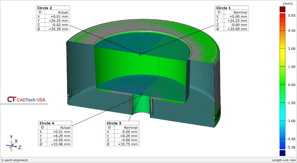
Figure 2: Nominal and Actual diameter of top and bottom of contact surface
Once the deviation analysis is completed, an inspection report is generated showing the different snapshots of the analysis with a summary of the values generated from the inspection. The inspection report is then sent to the customer. Depending on the project, different types of surface analysis and values can be generated to best meet the customer's needs.
Contact us if you have a project that requires a detailed First Article Inspection or a surface analysis between your CAD data and physical product.

